ActiveMQ EM400 Logic
The ActiveMQEM400 class handles the ingestion and processing of MQTT messages from Milesight EM400 series sensors. These sensors are primarily used for waste management (Bin level monitoring) and environmental sensing. The logic encompasses binary payload parsing, Bin state management, and automated task lifecycle control.
Terminology Mapping
In the context of waste management and bin monitoring, the generic system entities are mapped to the following domain-specific terms:
| System Term | Domain Mapping |
|---|---|
Site |
Sector |
Building |
Route |
Level |
Road |
Area |
Area |
Asset |
Bin |
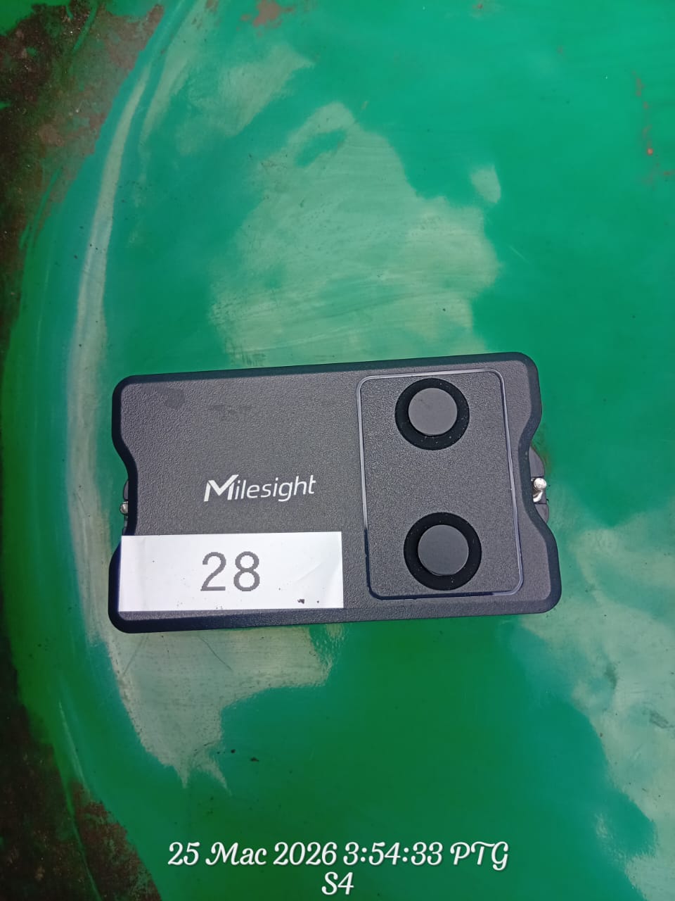
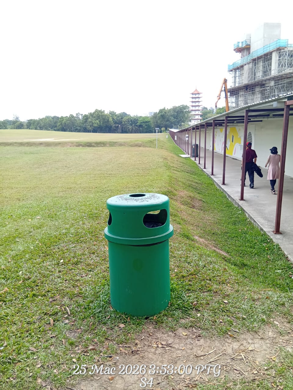
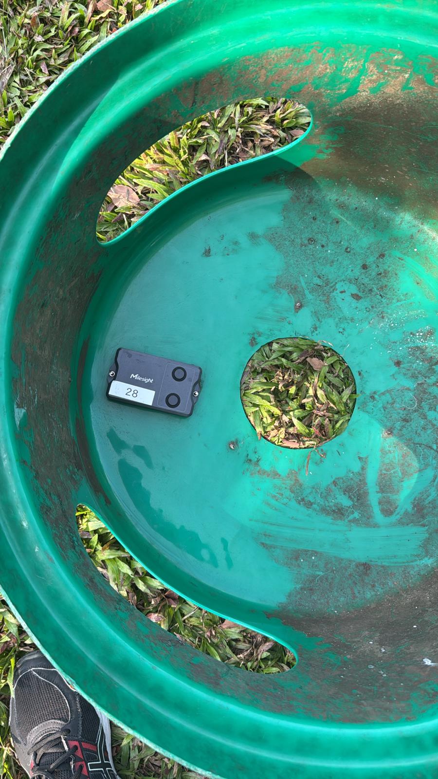
Hardware & Installation
The Milesight EM400 is a robust LoRaWAN/NB-IoT sensor designed for harsh environments. Below are visual references for the hardware and its typical installation in a waste management context.
Data Process Flow
The following diagram illustrates the sequential logic executed within the system for every incoming sensor message.
Header Parsing
Every message starts with a metadata header containing device identification and versioning information. The serial number is the primary key used to link the message to a specific Bin in the system.
| Field | Length (Hex Chars) | Description |
|---|---|---|
start |
2 | Packet start identifier. |
id |
4 | Packet ID. |
sn |
32 | Critical Device Serial Number (ASCII). |
imei / imsi |
30 / 30 | Cellular identifiers (ASCII). |
iccid |
40 | SIM Card identifier (ASCII). |
signal |
2 | RSSI Signal strength. |
Data Channels
The payload follows a structured format where the system iterates through the data to extract specific sensor readings.
| Channel | Type | Data Point | Processing Logic |
|---|---|---|---|
01 |
75 |
Battery Level | Integer percentage. |
03 |
67 |
Temperature | Decimal value in Celsius. |
04 |
82 |
Distance | Measured distance in millimeters. Used to calculate the fill level. |
05 |
00 |
Position | Device orientation status. |
06 |
88 |
GPS Location | Latitude and Longitude coordinates. |
84 |
82 |
Alarm + Dist | Distance reading with an additional alarm status flag. |
Fill Percentage Formula
The distance reading from the sensor is converted into a fill percentage using a linear calculation based on the configured minimum and maximum read distances.
Fill % = ((MaxDistance - CurrentDistance) / (MaxDistance - MinDistance)) * 100Logic Constraints:
- 100% Full: If the current distance is less than or equal to the minimum distance.
- 0% Full: If the current distance is greater than or equal to the maximum distance.
- Default Settings: If not specified, the system defaults to a minimum of 300mm and a maximum of 700mm.
Example
With a minimum of 300mm and a maximum of 700mm, a distance reading of 400mm results in:
((700 - 400) / (700 - 300)) * 100 = 75%
Business Logic
1. Alarm Fallback Mechanism
When an alarm packet is received, the sensor may omit certain data points. To maintain data integrity, the system automatically retrieves the last known values for battery, temperature, and position from the historical sensor data.
2. Genuine Point Logic (GPS Filtering)
To filter out GPS inaccuracies and "drift", the system employs a validation process:
- If a new coordinate is more than 200 meters from the current Bin location, it is marked as a potential move.
- The Bin location is only updated after 5 consecutive valid points are received from the same general area.
- Any point within the 200-meter radius resets the validation counter.
3. Automated Task Lifecycle & Historical Back-tracking
The system processes sensor data in chronological order. If a message contains a batch of historical data points, the system calculates the estimated time of occurrence for each point.
Historical Time Calculation
For each data point in a batch, the system estimates the actual time it occurred based on the message timestamp and the position in the batch. This ensures that historical events are recorded accurately.
| Condition | Action |
|---|---|
| Fill level reaches threshold | Create or Update Task: If no task exists for today, a new Public Task is created. If a normal task already exists, it is elevated to a high-priority feedback task. |
| Fill level drops below threshold |
Auto-Close (Fallback): If the cleaner fails to manually close the task via the mobile app, the system will automatically mark the task as completed when the sensor detects the bin is empty.
The task is closed using the estimated time when the empty state was first detected, ensuring accurate reporting. |
4. Task Closing Mechanism (Dual-Closing)
The system supports two methods for closing a task to ensure operational flexibility:
- Primary Method (Manual Close): When a Cleaner receives a notification and completes the cleaning, they manually close the task within the mobile app. This is the preferred method.
- Secondary Method (Auto-Close Fallback): If the cleaner does not close the task via the app, the system automatically closes it once the next sensor readings indicate the Bin has been emptied.
5. Batch Processing Edge Case: Empty & Refill
In scenarios where a Bin is emptied and then refilled within the same data batch:
- The system processes the "Empty" point, finds the open task, and automatically closes it.
- The system then processes the "Refilled" point and creates a new task for the same day.
- To prevent redundant alerts, the system ensures only the latest state is notified to users.
6. Operation Process Flow (End-to-End)
The following flow describes the complete operational cycle, from the initial alert to the final task closure.
Cleaner Activation & Workflow
When a Cleaner is notified of an alert, the system provides the necessary context for a rapid response:
- High-Priority Alert: Distinct sounds and vibrations ensure the notification is noticed immediately.
- Immediate Context: The app shows the Bin ID, its location on a map, and the current fill percentage.
- Task Completion: The cleaner is expected to close the task via the app upon finishing the service.
- System Fallback: If the app is not used to close the task, the system relies on the sensor to verify the work is done and close the task automatically.
Proof of Service
The automatic verification step acts as a digital "Proof of Service". By using sensor data to confirm the bin is empty, the system ensures that collection actually occurred, providing high-confidence reporting for management.
Sensor Accuracy & Environmental Factors
While the sensor is highly reliable, certain factors can lead to measurement inaccuracies:
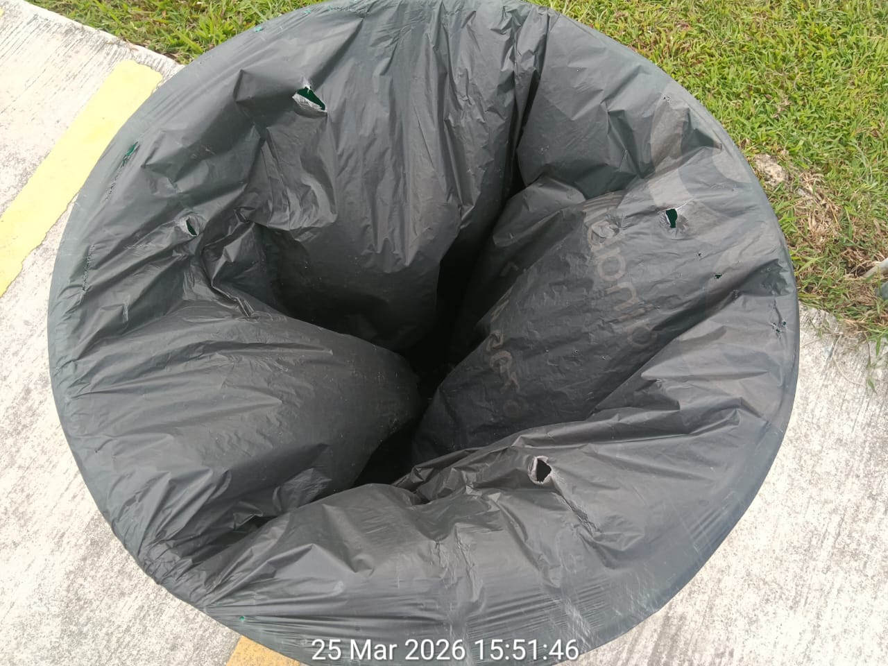
Common Inaccuracy Scenarios
- Trash Bag Interference: A billowing or poorly fitted trash bag can block the sensor, leading to a false "Full" alert.
- Irregular Load Distribution: Waste piled directly under the sensor will report a higher fill level than waste at the edges.
- Condensation & Debris: Moisture or debris on the sensor lens can scatter the signal, resulting in erratic readings.
- Bin Orientation: If the Bin is tilted or knocked over, the sensor may measure the side wall or the ground instead of the waste level.
Notifications
Upon task creation, the system triggers push notifications to the mobile app.
- Targeting: Notifications are sent to the specific cleaners and supervisors assigned to the bin's sector and area.
- Message Content: The notification includes the bin details and the current fill level.
- Optimization: If multiple data points are processed at once, only the notification for the latest state is sent.